PRODUCT LIST
Contact us

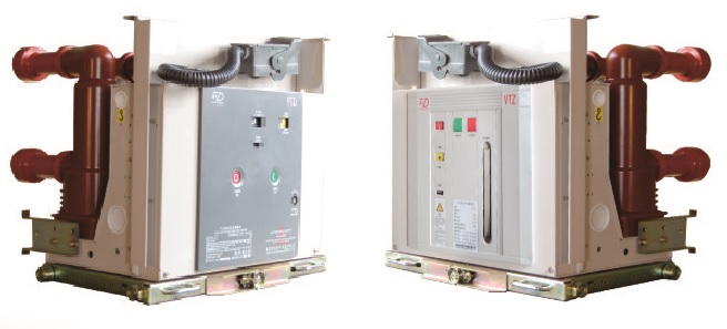
VTZ-12 Indoor High Voltage Vacuum Circuit Breaker

1.General Description
ZN28-12K fixed type indoor MV vacuum breaker (hereinafter :circuit breaker) is a component of 12KV&50HZ indoor switchgear which is accordance with GB1984-2003,JB3855-1996,DL403-2000 and IEC6227100.
2.Applying conditions:
Ambient temperature;-20℃----+40℃
Relative humidity:daily average ≤95%,monthly average ≤90%
Seismic intensity :≤8
Saturated vapor pressure:daily average ≤2.2kPa,monthly average≤1.8kPa;
Altitude:≤2000m;(Not including special requirement)
Service environment:should be avoided fire, explosion risk, serious pollution, chemical corrosion and violent vibration
1.Adopt module operating mechanism,integrated stored energy hand shank and reasonable whole structure.
2. Use module design to easy dis-assemble and replace broken parts. ;
3.Adopt Solid-closure technology in primary circuit to improve insulation and achieve free maintenance.
4.Long life,The circuit breaker meet M2 &E2.
5.Own excellent breaking property to make and break inductance and capacitance.
6.suitable for KYN-28and XGN-12 and replace VD4-12 and HVX-12.
7.Fixed and handcart assembled unit to meet different requirement of switchgear and circuit breaker.
Equipped with fuse handcart,disconnector handcart and voltage transformer handcart.
3.Overall and assembled dimensions


2. Assembled dimensions of Circuit breaker &switchgear
1)Assembled dimensions of VTZ Circuit breaker &switchgear(800mm width)
Rated current(A) | 630 | 1250 | 1600 |
Rated short circuit breaking current(kA) | 20,25,31.5 | 25,31.5,40 | 31.5,40 |
Dimension of fixed contact D(mm) | φ35 | φ49 | φ55 |
5.Technical specification
1、VTZ Technical specification(Table 1)
Table 1
No. | Item | Unit | Data | ||||||
1 | Rated voltage | kV | 12 | ||||||
2 | Rated frequency | Hz | 50/60 | ||||||
3 | Rated power frequency withstand voltage/1min | kV | 42 | ||||||
4 | Rated lighting impulse withstand voltage | kV | 75 | ||||||
5 | Rated current | A | 630 | 1250 | 1600 | 2000 | 2500 | 3150 | 4000* |
6 | Rated short circuit breaking current Rated short time withstand current(4s) | kA | 20 | ||||||
25 | 25 | ||||||||
31.5 | 31.5 | 31.5 | 31.5 | 31.5 | |||||
40 | 40 | 40 | 40 | 40 | 40 | ||||
50 | |||||||||
7 | Rated short circuit making current(peak) Rated withstand current(peak) | kA | 50 | ||||||
63 | 63 | ||||||||
80 | 80 | 80 | 80 | 80 | |||||
100 | 100 | 100 | 100 | 100 | 100 | ||||
125 | |||||||||
8 | Rated short circuit breaking times | Times | 30,50 * | ||||||
9 | Rated duration of short circuit | s | 4 | ||||||
10 | Rated operating sequence | O-0.3s-CO-180s-CO * | |||||||
11 | Mechanical life | Times | 30000 | ||||||
12 | Rated single capacitor bank breaking current | A | 400 | ||||||
13 | Rated back to back capacitor bank breaking current | A | 400 | ||||||
Remark:
1.No.12 &No.13 nominal parameter are offered while user need.
2.Switchgear should be equipped with forced cooling when rated current is 4000A.
3.Rated short circuit breaking times are 50 times while Rated short circuit breaking current ≤31.5KA.
4.Rated short circuit breaking times are 50 times while Rated short circuit breaking current ≥31.5KA.
5.Rated operating sequence is O-180s-CO-180s-CO while Rated short circuit breaking current ≥40KA
2、Characteristic parameter after VTZ VCB assembly adjusted(table2)
Table 2
No. | Item | Unit | Data | |||
1 | Clearance between open contacts | mm | 9 ± 1 | |||
2 | Contact travel | 3.5 ± 0.5 | ||||
3 | Bounce time of contact closed | ms | ≤ 2(1600A and under),≤ 3(2000A and above) | |||
4 | Non simultaneity of 3 phase contact opened&closed | ≤ 2 | ||||
5 | Distance between phase | mm | 210±1.5 | 275±1.5 | ||
6 | Rated short circuit breaking current | kA | 20~25 | 31.5 | 40 | 50 |
7 | Contact force of contact closed | N | 2200±200 | 3100±200 | 4500±200 | 6000±500 |
8 | Average opening speed | m/s | 1.1±0.2(Contact opened~6mm) | |||
9 | Average closing speed | 0.6±0.2 | ||||
10 | Opening time | ms | 20~50 | |||
11 | Closing time | 30~70 | ||||
12 | Wearing for contract permitted | mm | ≤3 | |||
13 | Resistance for each main circuit | μΩ | ≤50(630A)≤45(1250~1600A) | |||
≤35(2000A) ≤25(2500 and above) | ||||||
6.Secondary connection diagram

